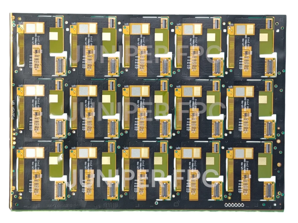
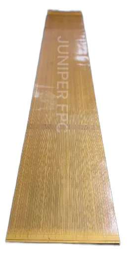
Flex circuit stackup is an essential element in the design and performance of flexible printed circuit boards (FPCBs).
A well-constructed stackup ensures the circuit board functions effectively, offering flexibility, durability, and reliable electrical performance. In this article, we’ll explore the details of flex circuit stackup, its components, and how it affects the performance of flexible circuits.

What Does Flex Circuit Stackup Mean?
Flex circuit stackup refers to the arrangement of layers within a flexible printed circuit board. These layers typically consist of conductive materials, insulation, and adhesives, each serving a specific purpose in the functionality of the flex PCB. The stackup design determines the electrical properties, mechanical strength, and flexibility of the circuit.
The most common materials used in flex circuit stackups include copper for electrical conductivity, polyimide for flexibility, and adhesive materials to bond the layers together. These components work in harmony to ensure the flex PCB’s reliability, especially in dynamic applications like aerospace, automotive, and medical devices.
Why is Stackup Important in Flex Circuit Design?
The design of the stackup plays a significant role in the overall performance of a flex PCB. It affects signal integrity, mechanical strength, and the board’s ability to bend without damage. A well-designed stackup can prevent issues such as signal loss or interference and ensure that the PCB can withstand the mechanical stresses of its intended application.
For instance, a poor stackup design could result in weak signal transmission or reduced durability. In contrast, a properly optimized stackup enhances the electrical performance, particularly in high-speed circuits, while ensuring that the board maintains its flexibility and reliability in real-world conditions.
Common Types of Flex Circuit Stackups
There are several types of stackups used in flex circuit design, depending on the complexity and application of the PCB. These include:
- Single-Sided Stackup: This is the simplest type of stackup, with only one conductive layer. It’s commonly used in basic applications that don’t require complex circuits.
- Double-Sided Stackup: In this design, both sides of the PCB are conductive, allowing for more complex connections and greater circuit density. Double-sided stackups are often used in more intricate designs.
- Multi-Layer Stackup: These stackups are typically used for more advanced circuits, such as rigid-flex PCBs or high-performance designs. Multi-layer stackups offer the highest performance and are essential for miniaturized devices that require more layers of circuitry, like medical devices and aerospace equipment.

How to Design a Flex Circuit Stackup?
Designing an effective flex circuit stackup requires careful consideration of the materials used, the number of layers, and how the layers will be aligned. Factors like the operating environment, thermal requirements, and bending radius all impact the final design.
Flex PCB manufacturers typically collaborate with product engineers to ensure that the stackup design meets the specific requirements of the application. Material choices are crucial—using high-quality materials like polyimide for flexibility and copper for conductivity ensures that the final product performs optimally.
A good stackup design balances electrical properties and mechanical strength. For example, a thinner PCB might offer greater flexibility, but it could also sacrifice some mechanical strength. By selecting the right material and layer thickness, designers can achieve the perfect balance between performance and durability.
What Material is Used in Flex PCB Stackup?
The materials used in a flex PCB stackup are critical to the performance of the circuit. The primary materials are:
- Copper: This conductive material is used for creating electrical paths on the PCB.
- Polyimide or PET: A flexible and heat-resistant material that serves as the insulation layer, providing the necessary flexibility for bending and movement.
- Adhesive: The adhesive material bonds the layers together and ensures structural integrity.
These materials work together to provide a flexible yet durable flex PCB that meets the electrical and mechanical requirements of various applications.
How Thick is a 2 Layer Flex PCB?
A 2-layer flex PCB typically ranges from 0.15mm to 0.5mm in thickness. The exact thickness will depend on factors such as the materials used, the design requirements, and the application.
Thicker designs offer more mechanical strength but may compromise some flexibility, while thinner designs provide greater flexibility but may lack the structural integrity required for certain applications. The copper layer thickness also plays a role in determining the overall thickness of the PCB.
What is the Adhesive in Flex PCB?
The adhesive in a flex PCB stackup is crucial for bonding the layers together while maintaining flexibility. Common adhesive materials include:
- Acrylic-based Adhesive: Known for its good bonding properties and flexibility.
- Epoxy-based Adhesive: Offers strong adhesion and durability, especially in high-temperature environments.
- Polyimide-based Adhesive: Often used in high-performance applications due to its excellent heat resistance and flexibility.
The adhesive type chosen depends on the application, the desired flexibility, and the thermal conditions the PCB will face.
How Thick is the Copper in a Flex PCB?
The copper thickness in a flex PCB is typically measured in ounces per square foot (oz/ft²), with common thicknesses ranging from 0.5 oz/ft² to 2 oz/ft². Thicker copper is used for high-power applications, while thinner copper is used in signal-level circuits to reduce weight and improve flexibility.
The copper thickness influences the board’s electrical conductivity and its ability to dissipate heat, making it a crucial factor in the design of high-performance circuits.
What is the Minimum Radius for a Flex PCB?
The minimum bend radius refers to the smallest radius at which a flex PCB can be bent without causing damage to the circuit. This is an important consideration when designing flexible PCBs for applications that require bending or movement.
The minimum bend radius typically ranges from 0.5mm to 2mm, depending on the thickness of the PCB and the materials used. Thinner PCBs with higher-quality copper tend to have smaller bend radii, allowing for greater flexibility.
What is the Thickness Tolerance of a Flex PCB?
Thickness tolerance refers to the allowable variation in the thickness of the PCB layers. For most flex PCBs, thickness tolerance ranges from ±10% to ±20%, depending on the material and the manufacturer’s specifications.
Precise thickness tolerance is essential for ensuring that the stackup remains uniform and performs consistently across all layers. Variations in thickness can affect the electrical properties of the circuit, especially in multi-layer flex PCBs such as 3-layer and 4-layer stackups.
Summary
Understanding flex circuit stackup is crucial for designing durable, high-performance flexible PCBs. The right choice of materials and careful attention to layer thickness, copper thickness, and adhesive selection ensures optimal functionality, flexibility, and reliability in demanding applications. Whether you’re designing a basic 2-layer flex PCB or a complex rigid-flex PCB, the stackup plays a key role in ensuring long-term performance.
